DIY Kit – Install Guide – WIP
!!IMPORTANT NOTES!!
!! This kit REQUIRES both soldering equipment and knowledge to install !!
It is highly suggested to purchase Start/Select + Dpad replacement boards with your DIY Kit. They will make this experience a LOT easier.
Link for Start/Select Replacement Boards.
Link for Dpad Replacement Boards.
Also Rock Band 4 on Xbox One/Series requires authentication, so if you are planning on playing that game, purchase our Authentication Cable upgrade .
Prerequisites
Required Tools (not included)
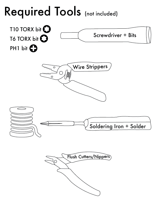
- Soldering Iron
- Solder
- Damp Sponge or Brass Sponge Iron Cleaner
- Screwdriver (or bits)
- PH1
- T10 TORX
- T6 TORX
- Other misc sized PH bits.
- Wire Stripper
- Flush Cutters/Nippers
Don’t have some of these tools? Here are our suggestions:
- Pinecil Soldering Iron (You will need a cable and power source as well. Highly suggest this because you get high end soldering performance for much less cost than popular brands)
- Kester Leaded Rosin-Core Solder
- Brass Sponge Iron Cleaner
- Screwdriver + Bit set
- Wire Strippers
- Flush Cutters/Nippers
Parts Included in DIY Kit
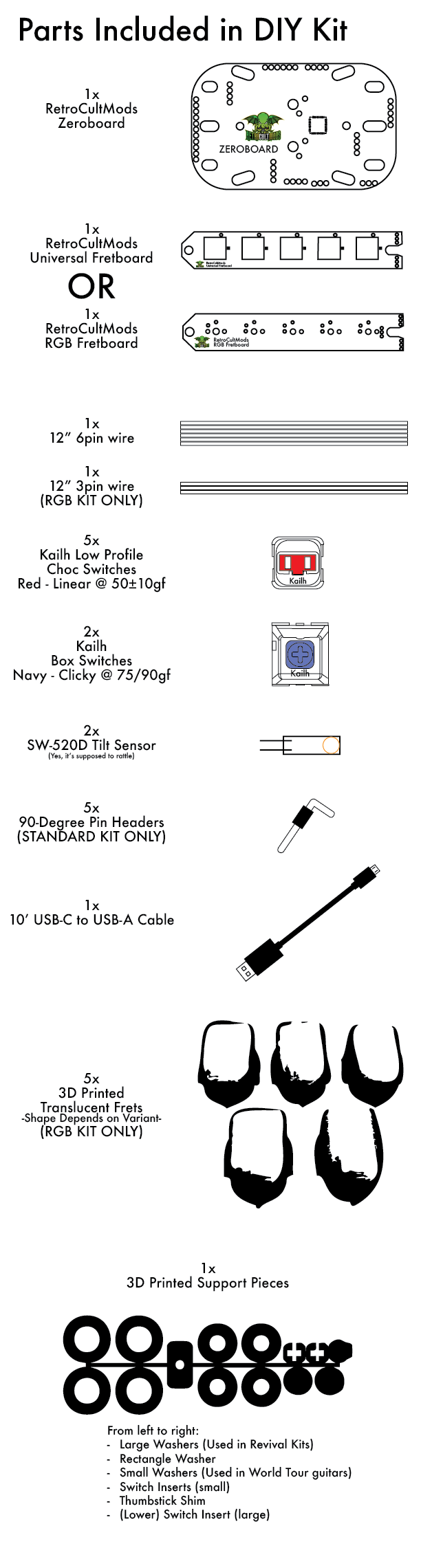
- [1] RetroCultMods Zeroboard
- Switches
- [2] Kailh Box Navy Switches
- [5] Kailh Low Profile Choc Red Switches
- One of the following fretboards (variants highlighted for clarity):
- Universal Standard Fretboard
- Includes [5] 90-Degree Pin Headers
- RGB Fretboard
- Includes [5] 3D Printed Translucent Frets (Shape depends on variant)
- Includes [1] 12″ 3 Pin Wire
- Universal Standard Fretboard
- [1] 12″ 6 Pin Wire
- [2] SW-520D Tilt Sensor
- [6] Screws
- [1] 10′ USB-C to USB-A Cable
- [1] 3D Printed Support Pieces
- [4] Strumboard Washers (Used with World Tour model)
- [4] Large Washers
- [1] Rectangular Washer
- [2] Small Switch Inserts
- [2] Large Switch Inserts
- [1] Thumbstick Shim (Wii Models)
Compatible Guitars

RedOctane Wii Les Paul
(GH3, Aerosmith)

RedOctane Wii Sunburst
(World Tour)

RedOctane Wii “GH5”
(GH5, Band Hero)

RedOctane XB360/PS3 Les Paul
(GH3, Aerosmith)

RedOctane XB360/PS3 Sunburst
(World Tour)

RedOctane XB360/PS3 “GH5”
(GH5, Band Hero)

RedOctane PS2 SG
(GH1, GH2)

RedOctane PS2 Kramer
(GH3)

RedOctane XB360 Xplorer
(GH2, GH3)

RedOctane PS2 Mayflash
(GH3)
Disassembly and Removal of Existing Components
Each guitar has it’s own process of disassembly and removal of existing components. Click the dropdown for your guitar.
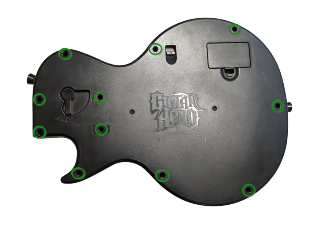
Xbox/Playstation Les Paul Disassembly
Opening the Xbox 360/Playstation 3 Les Paul
- Flip the controller over so the Guitar Hero logo on the back of the body is visible. Remove the neck from the body. Remove the following screws:
- Rear body shell – 9x T10 screws (remember the one under the Warranty sticker)T10
- Ensure that all of the screws are removed, and open the shell. We recommend starting to pry gently from the opening near the neck connector.
- Once the shell begins to open, slowly move down the rest of the shell until it pops open completely.
- Repeat this process for the neck, using the opening at the neck connector and working towards the headstock.
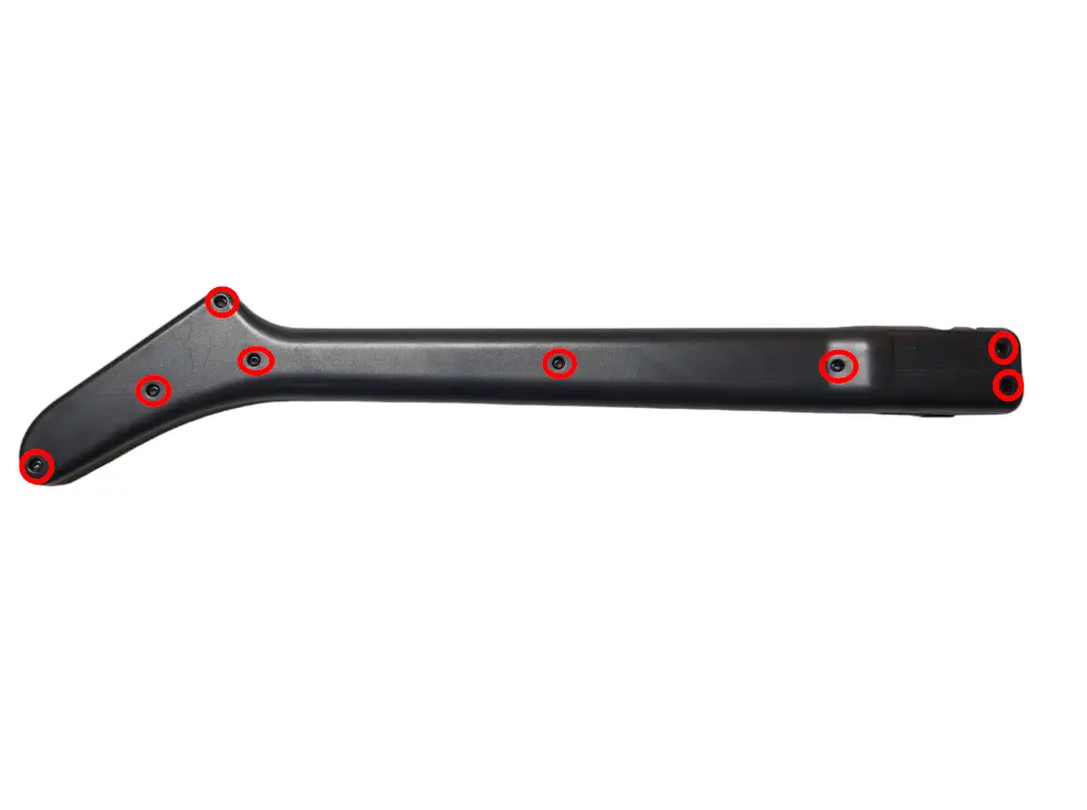
- Rear neck shell – 10x T10 screws
If the shell seems to gets stuck, DO NOT FORCE IT. Check to make sure you have removed all of the screws before continuing to pry the shell.
Removing Existing Les Paul Components
- Now its time to remove the stock boards that will be replaced with the new boards included in the kit. Xbox models will use T6 screws, and Playstation models will use PH1 screws.
- Remove the 2 PH1/T6 screws on the RJ11 (foot pedal) port. We can route the USB-C cable out of this hole.
- Remove the 4 PH1/T6 screws on the stock strumboard.
- If you purchased the Les Paul D-Pad Replacement Board, remove the 2 PH1/T6 screws the dpad board. RECOMMENDED
- If you purchased the Les Paul Start/Select Replacement Board, remove the 2 PH1/T6 screws on the start/select board. RECOMMENDED
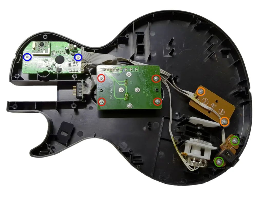
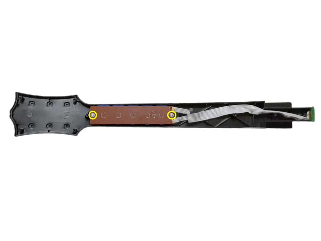
- Remove the 2 PH1/T6 screws on the stock fretboard.
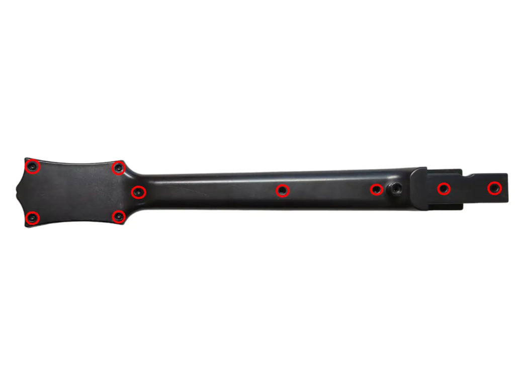
Necessary Body Modifications
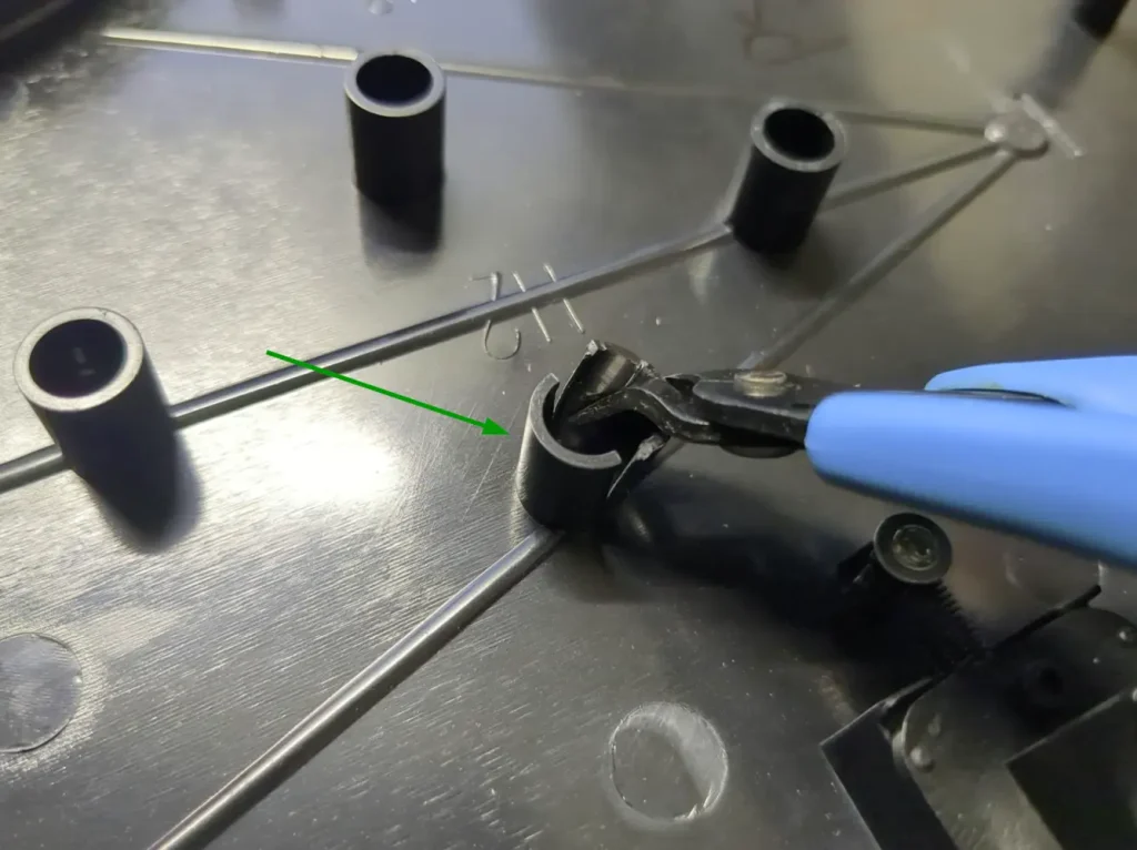
You will have to cut the following bits of plastic off of the body of the guitar using flush cutters.
- We will need to remove some supports from the rear body shell. The best way to do this is to make two cuts on each support, splitting them in half. Then slowly bend the two halves away from each other, and it should split off.
- Remove the sections of the rear neck shell highlighted in the picture. The support closest to the neck does not need to be removed.
The remaining plastic does not need to be perfectly flush for a proper fit, but you should clear away any jagged edges left behind from the cuts.
Xplorer Disassembly
Opening the Xplorer
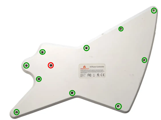
- Flip the controller over so the Red Octane sticker on the back of the body is visible. The type of screws used on the outside shells will depend on the model of your guitar:
95055/95605 – PH1 Screws
95157.805 – T10 Screws - Ensure that all of the screws are removed, and open the shell.
- Once the shell begins to open, slowly move down the rest of the shell until it pops open completely.
- Rear body shell – 11x screws
- The screw marked in red is longer than the others; remember this for when you put everything back together! Note that some Xplorers will not have a longer screw.
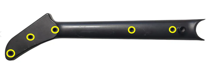
- Repeat this process for the neck, using the opening at the neck connector and working towards the headstock.
- Rear neck shell – 5x screws
If the shell seems to gets stuck, DO NOT FORCE IT. Check to make sure you have removed all of the screws before continuing to pry the shell.
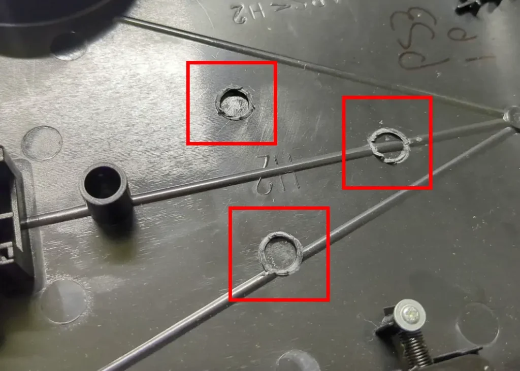
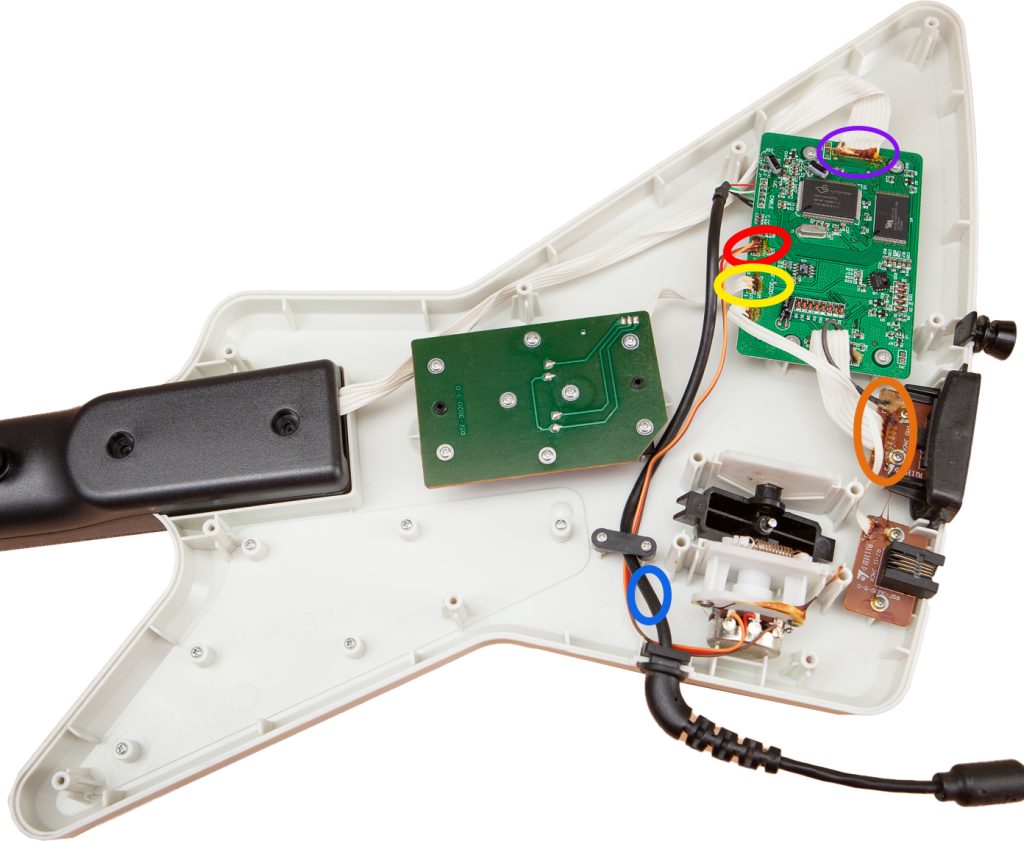
Cutting Wires
Note: You may want to unscrew the control board early.
- Cut the whammy cables at the connection point on the control board.
- Cut strumboard cable at the connection point on the control board.
- Cut headphone cables on the end of the headphone board, as close as you can to the board.
- Cut fretboard cable at the connection point on the control board.
- (READ CAREFULLY BEFORE YOU CUT) You can cut the power cable on either the boot end or control board end, but it depends on which you want to do.
- If you want to continue using the original Xplorer cable, cut the five colored wires as close as you can to the control board. You will want to buy our Xplorer Breakout Board if you do this.
- NOTE: DIY KIT NO LONGER SUPPORTS THE ORIGINAL XPLORER CONTROL BOARD
Removing Existing Xplorer Components
- Now its time to remove the stock boards that will be replaced with the new boards included in the kit.
- Remove the 4x screws on the stock Strumboard.
- Remove the 2x screws on the RJ11 (footpedal) port. (You can route your cable out of here if you decide to use the included USB-C cable)
- If you have the Xplorer Breakout Board, remove the 4x screws on the stock input board. (Keep all silicone pads and button pieces)
- We will not be removing the headphone board.
- Remove the 2x screws from the stock Fretboard. (We will not need the silicone pad)
World Tour / Sunburst Disassembly [WIP]
Opening the Sunburst
Move the faceplate latch to the unlocked position on the back of the body, then remove the faceplate by pulling upwards from the neck slot.
- Front body shell – 11x T10 screws
- Front body shell (neck) – 4x PH0 screws
- Rear neck shell – 11x T10 screws
Ensure that all of the screws are removed, and open the shell. I recommend starting to pry gently from the opening near the neck connector.
Once the shell begins to open, slowly move down the rest of the shell until it pops open completely.
Repeat this process for the neck, using the opening at the neck connector and working towards the headstock.
If the shell seems to gets stuck, DO NOT FORCE IT. Check to make sure you have removed all of the screws before continuing to pry the shell.
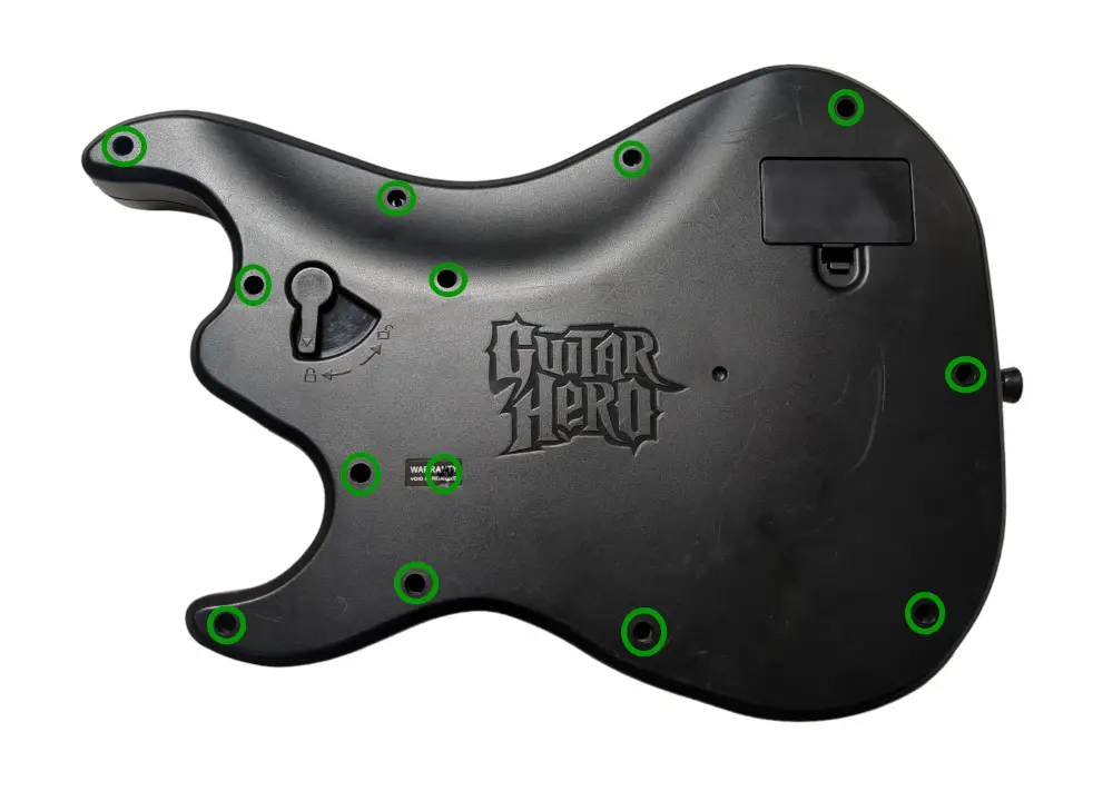
SG Disassembly
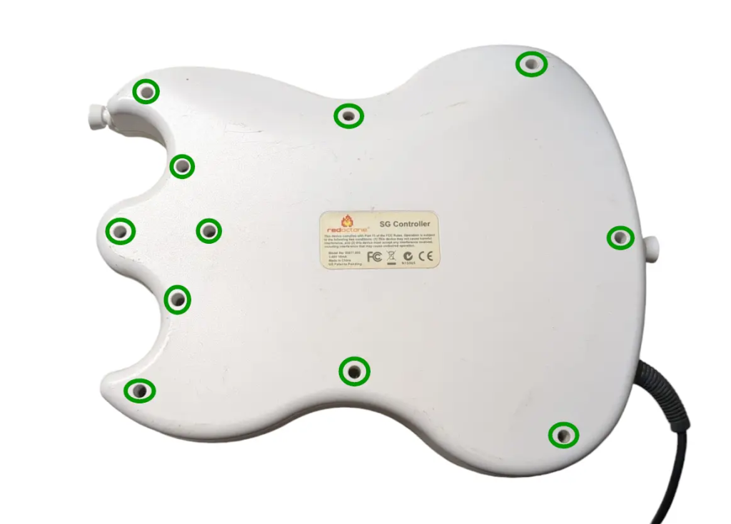
Opening the SG
- Flip the controller over so the Red Octane sticker on the back of the body is visible. Remove the following screws
- Rear body shell – 11x T10 screws (remember the one under the Warranty sticker)
- Ensure that all of the screws are removed, and open the shell. We recommend starting to pry gently from the opening near the neck connector.
- Once the shell begins to open, slowly move down the rest of the shell until it pops open completely.
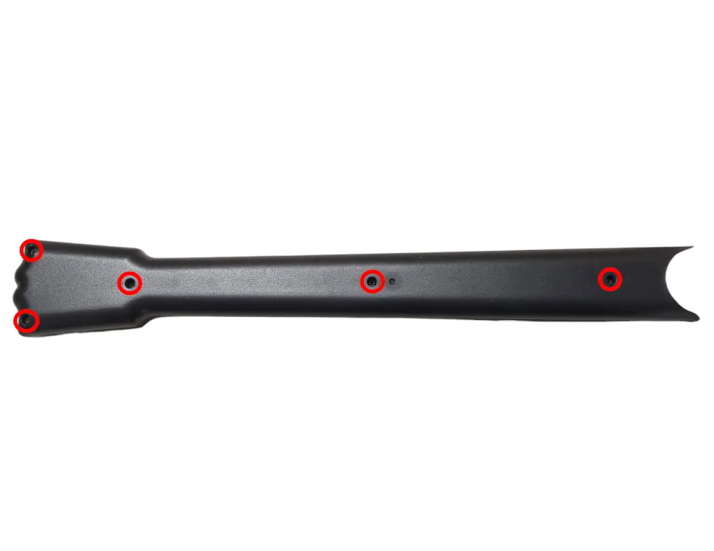
- Repeat this process for the neck, using the opening at the neck connector and working towards the headstock.
- Rear neck shell – 5x T10 screws
If the shell seems to gets stuck, DO NOT FORCE IT. Check to make sure you have removed all of the screws before continuing to pry the shell.
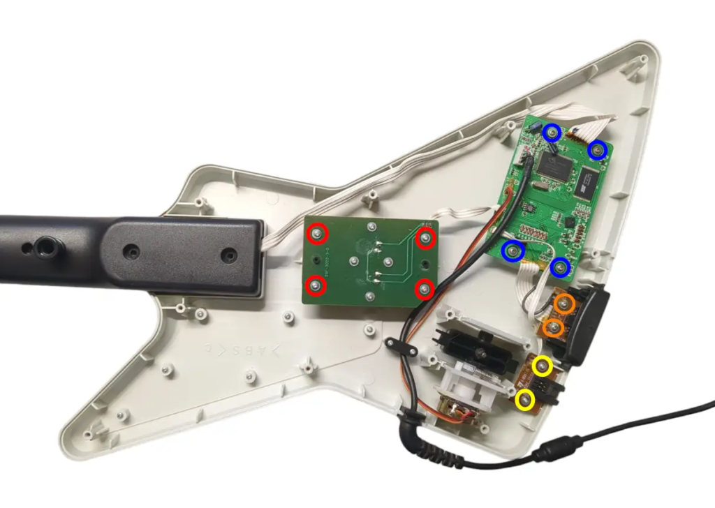
Cutting Wires
- Cut the whammy cables as close to the strum board as you can.
- Cut the start/select board cables as close to the strum board as you can.
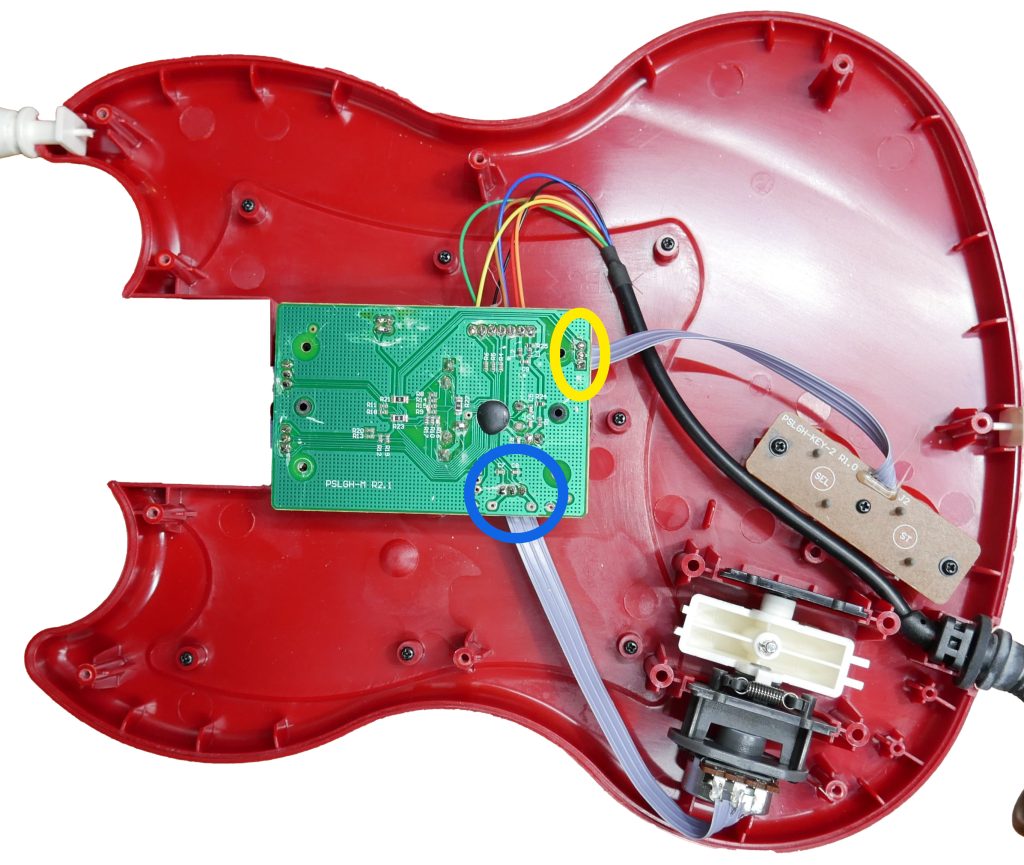
Removing Existing Components
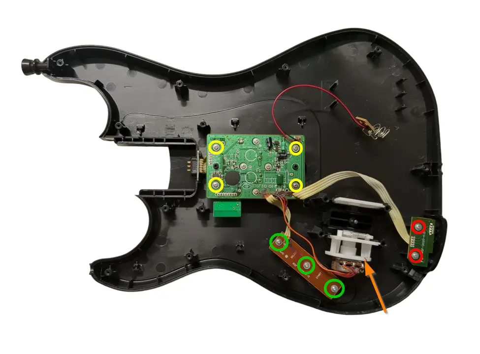
Now its time to remove the stock boards that will be replaced with the new boards included in the kit.
- Remove the 4x PH1 screws on the stock strumboard.
- (Optional, if you bought the SG Start/Select Replacement Board) Remove the 3x PH1 screws on the stock start/select board.
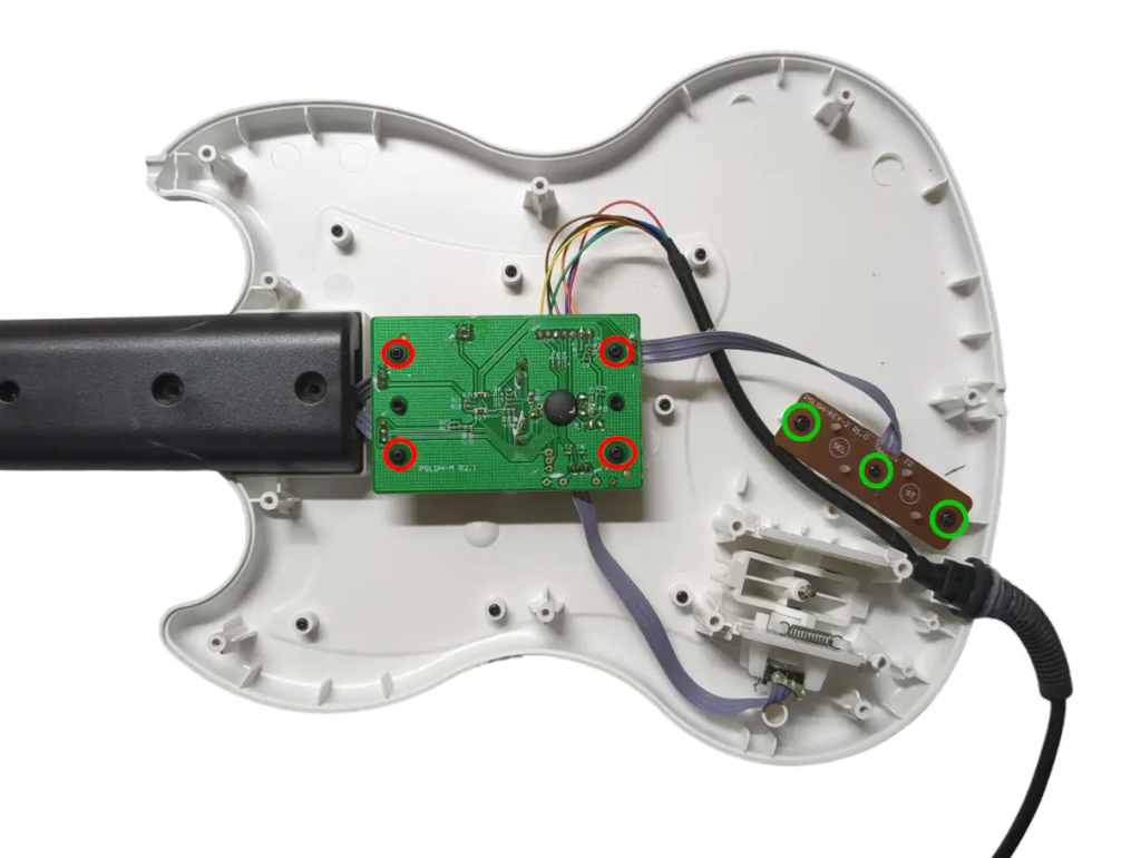
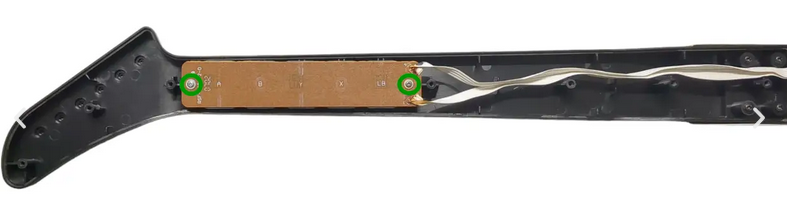
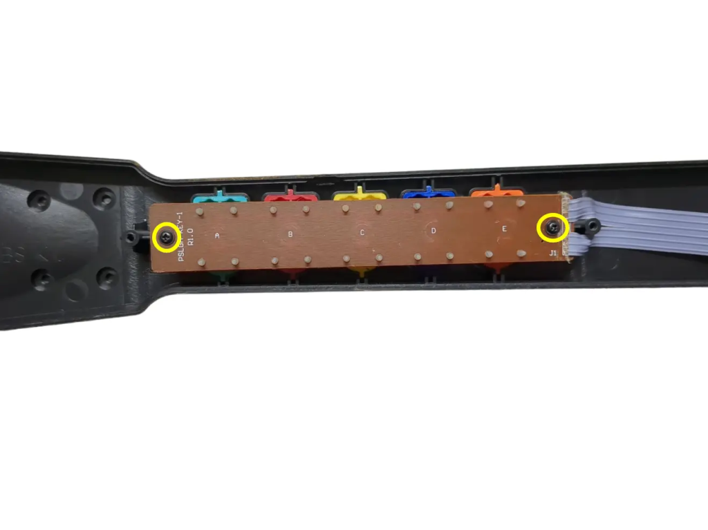
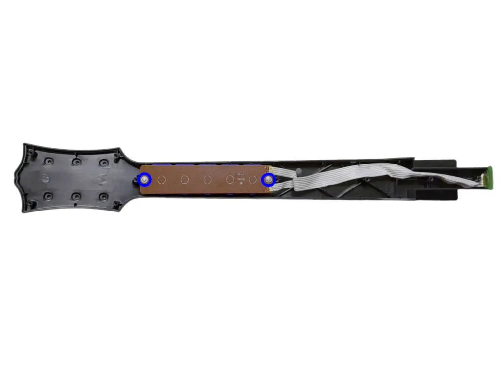
- Remove the 2x PH1 screws on the stock fretboard.
Kramer Disassembly
Opening the Kramer
Flip the controller over so the Guitar Hero logo on the back of the body is visible. Remove the neck from the body. Remove the following screws:
- Rear body shell – 13x T10 screws (remember the one under the Warranty sticker)
- Rear neck shell – 8x T10 screws
Ensure that all of the screws are removed, and open the shell. I recommend starting to pry gently from the opening near the neck connector.
Once the shell begins to open, slowly move down the rest of the shell until it pops open completely.
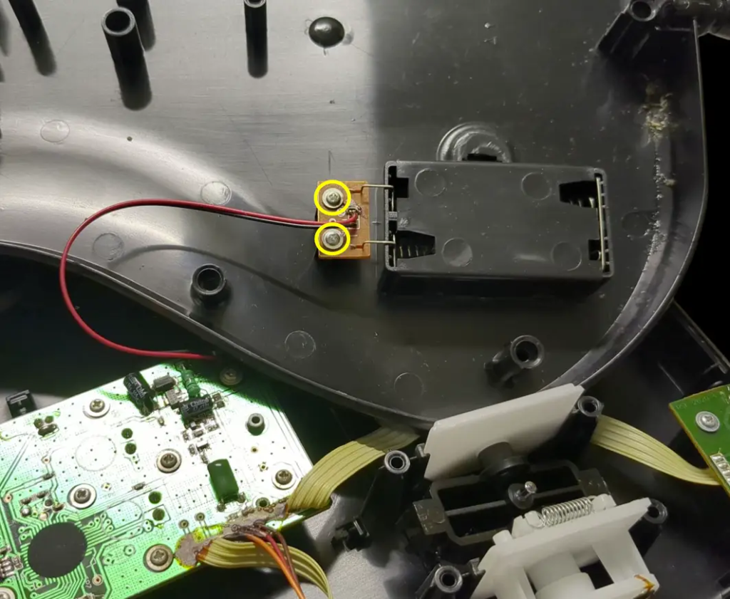
- Remove the battery board by unscrewing the 2x PH1 screws holding it down
- Repeat this process for the neck, using the opening at the neck connector and working towards the headstock.
If the shell seems to gets stuck, DO NOT FORCE IT. Check to make sure you have removed all of the screws before continuing to pry the shell.
Removing Existing Kramer Components
Now its time to remove the stock boards that will be replaced with the new boards included in the kit. For most models these boards will use PH1 screws, but some use T6.
- Remove the 2 screws on the RJ11 (foot pedal) port.
- Remove the 4 screws on the stock strumboard.
- Remove the 2 screws on the stock fretboard.
Remove all internal boards and the stock whammy component and store them or dispose of them. We should now be left with an empty shell.
Mayflash Disassembly [WIP]
Wii Les Paul Disassembly [WIP]
Wii World Tour / Sunburst Disassembly [WIP]
Wii GH5 Disassembly [WIP]
Soldering
INFO YOU NEED TO KNOW:
Soldering Iron temperature: 600°F or 315°C (Leaded Solder)
675°F or 360°C (Lead Free Solder). I personally use the hotter temperature with leaded solder.
Cold Joints can appear as a bubble or a more matte finish on your solder joint. If this happens, hold the iron and melt the solder again, but hold your iron there briefly so the heat transfers to the pins properly.
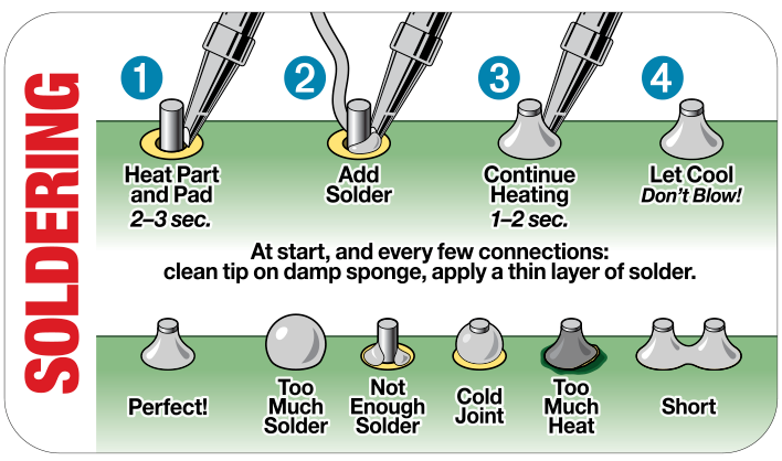
Tinning Your Iron’s Tip is a good habit when beginning a solder job. What you do is:
- Turn on your iron and set your it to the proper soldering temperature if it isn’t already set
- Put a little bit of solder on the tip of your iron, just enough to coat the part you solder with.
- Clean the solder off of it using a damp sponge or brass wool. You will see that the tip is shiny. That means it’s tinned!
Universal Fretboard Switches
Click here to see Universal Fretboard Switch Soldering Guide
Necessary Components:
- Universal Fretboard
- Kailh Choc Low Profile Red switches
- 90-degree Pin Headers
The Universal Fretboard soldering process is a bit more complex. Follow the fret section in the following video:
RGB Fretboard Switches [NEED IMAGES]
Click here to see RGB Fretboard Switch Soldering Guide
Necessary Components:
- RGB Fretboard
- 5x Kailh Choc Low Profile Red switches
Soldering switches to our RGB Fretboard is easy.
- Insert the Kailh Choc Low Profile switches into the fretboard, they will only go one way. Start with the two on the far ends.
- Flip the board over and push the PCB down to ensure that the switches are flush against it. Doing this on a hard surface will help.
- Tin your solder tip and clean it.
- Solder the switch pins to the fretboard.
- Repeat the process until you’ve soldered all five switches to the fretboard.
Note: After soldering a switch, look closely to see if the switch is as close to the fretboard as possible. We want it to be as flush as can be. You will be able to tell at the end if they are positioned correctly if you look at all the switches in line.
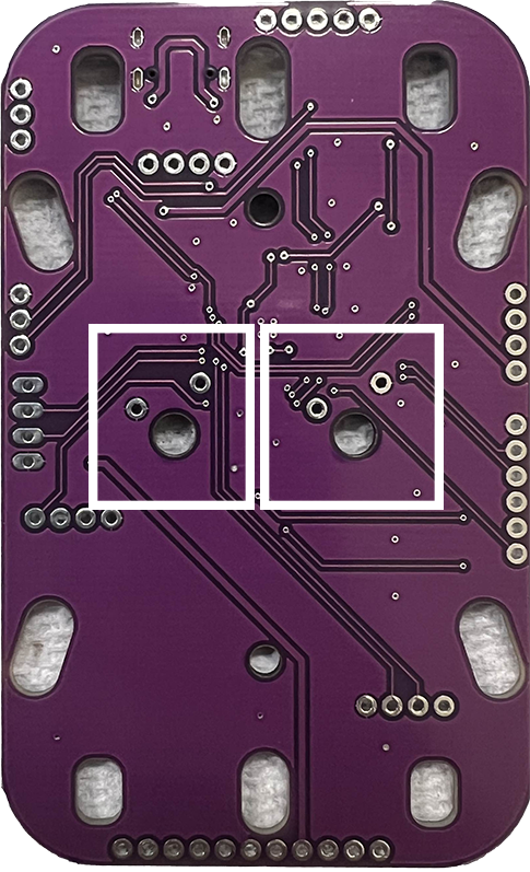
Zeroboard/Strumboard Switches [NEED IMAGE]
Click here to see Zeroboard/Strumboard Switch Soldering Guide
Necessary Components:
- Zeroboard (Strumboard)
- Kailh Box Navy switches
- Flip the Zeroboard over to the backside. This side does not have any text on it.
- Insert the Kailh Box Navy switches into the sockets, indicated in the image below.
- The board will then look like this:
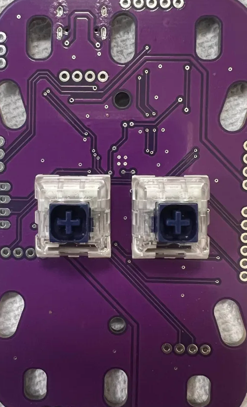
- After you’ve inserted the switches, use a piece of tape to hold the switches to the Zeroboard.
[Insert image with taped switches here]
- Flip over the Zeroboard and solder the four pins, two per switch. Be careful to not touch any other components with the soldering iron.
Fretboard to Strumboard [WIP]
Click here to see Fretboard to Strumboard Soldering Guide
Necessary Components:
- Standard or RGB DIY fretboard
- Zeroboard (strumboard)
- 12″ 6 Pin Wire (2 if you have RGB)
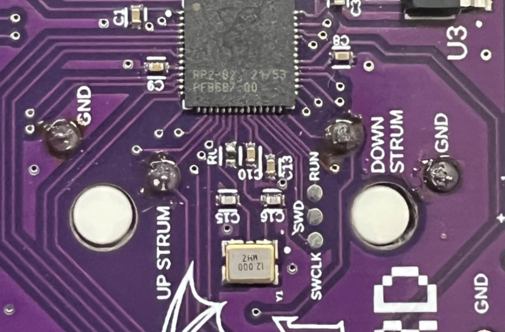
Whammy [NEED IMAGES]
Click here to see Whammy Soldering Guide
There are three wires that come from the whammy potentiometer. You will solder them to the pins marked VCC, ADC, and GND, closest to the whammy assembly itself.
MAJOR NOTE: THE MIDDLE WIRE WILL ALWAYS GO TO THE MIDDLE PIN, ADC.
- Tear the whammy cable into three individual wires
- Strip the wires, leaving about half a CM of bare wire.
- Insert each wire into their respective holes. The side ones can be in either hole, so wire whichever is easiest.
- Tin your soldering iron tip and clean it.
- Solder the wires.
Start/Select and Replacement Boards [WIP]
Click here to see Start/Select and Replacement Board Soldering Guide
Authentication Cable
Click here to see Authentication Cable Soldering Guide
Necessary Components:
- Refer to the following image for proper pinout:
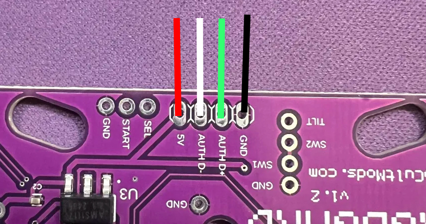
RED – VBUS
WHITE – AUTH –
GREEN – AUTH +
BLACK – GND
- Since our Authentication Cable has pins attached, you can insert them into the respective holes and bend 90 degrees so that it’s easy to solder.
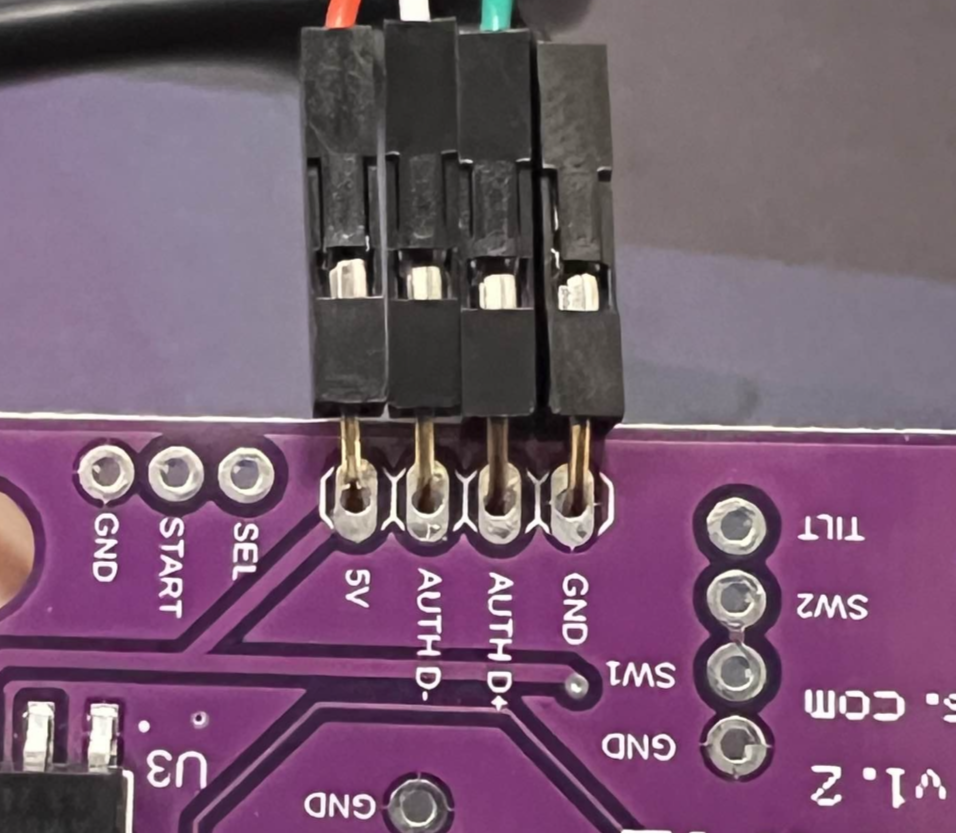
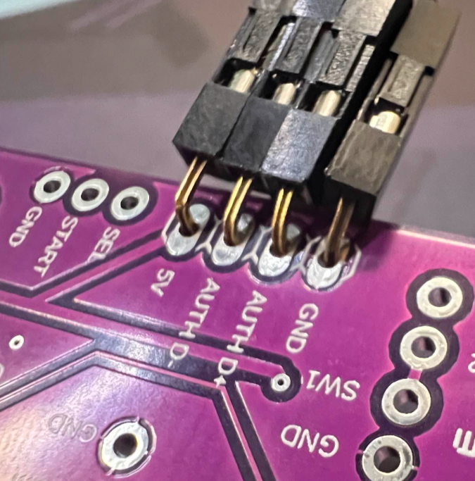
- Tin your soldering iron tip and clean it.
- Solder the pins.
- We now need to test and make sure that it’s wired correctly.
- Plug your Zeroboard into your computer, then open RCM Programming Tool. Click Configure. You will see that there is a dropdown tab that says “USB Host Devices : 0”.
- With the Zeroboard still plugged in, plug a gamepad into the authentication cable you just soldered on.
- Observe if “USB Host Devices” changes to 1.
- If it does, that means you have installed the authentication cable correctly!
Programming and Setup
Requirements
- Installed DIY Kit
- A computer that uses Windows, macOS, or Linux
- The latest revision of RCM Programming Tool
Click here for a step-by-step programming guide.
- Download and open the RCM Programming Tool.
- Plug your guitar into your computer. You will see it appear with “Configure” and “Reset to factory” buttons.
- Click “Configure“

- You will be taken the configuration page where, on the left side, there is a dropdown for you to change presets.
When switching to a different preset, click it, then click “Save Settings”.

- You will want to wait until the bar at the bottom reaches 100% and says Status: Done.

Final notes:
You will need to calibrate for guitars and gamepads. See the following section for specifics.
Tilt Tuning
Tilt will not function properly until calibrated.
Click here for a step-by-step Tilt Tuning Guide.
Whammy Tuning
Whammy will not function until calibrated.
Click here for a step-by-step Whammy Tuning guide.
- First, we must open the Whammy dropdown menu.
- Click on tab and a menu will pop up.
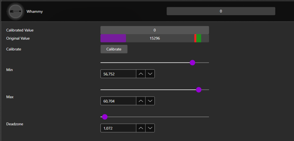
- Click Calibrate!
- Then, don’t touch your whammy bar and then click Next.
- After that, push your whammy bar down as far as it can go without overdoing it. Hold it there, then click Next.
- Now you have to set Deadzone. Push the whammy bar in a little bit and you can see the value go up a little bit. Look for a point where the whammy won’t activate on it’s own. Hold it there, then click Next.
- You’re done! Click Save Settings on the left side. After it’s done, give it a try! You can manually adjust the deadzone with the sliders as well if you’d like to tweak your settings.

Troubleshooting
My DIY Kit Guitar is failing to appear in the RCM Programming Tool
There are various reasons for this occurring.
Sometimes just unplugging it and plugging it back in will help or restarting the programming tool.
If unplugging and replugging doesn’t work, try a different USB-C cable.
Lastly, you may need to hard reset the device. Holding the reset button (small little button on top of the adapter) while plugging the adapter in will put it into recovery mode, which you can then open the RCM Programming Tool and erase and reset to factory.
If this doesn’t work, send us an email at support@retrocultmods.com