Xbox 360 Xplorer – Revival Kit Guide – WIP
Introduction
This is an instructional guide for the RetroCultMods Revival Kit for the Xbox 360 Gibson Xplorer.
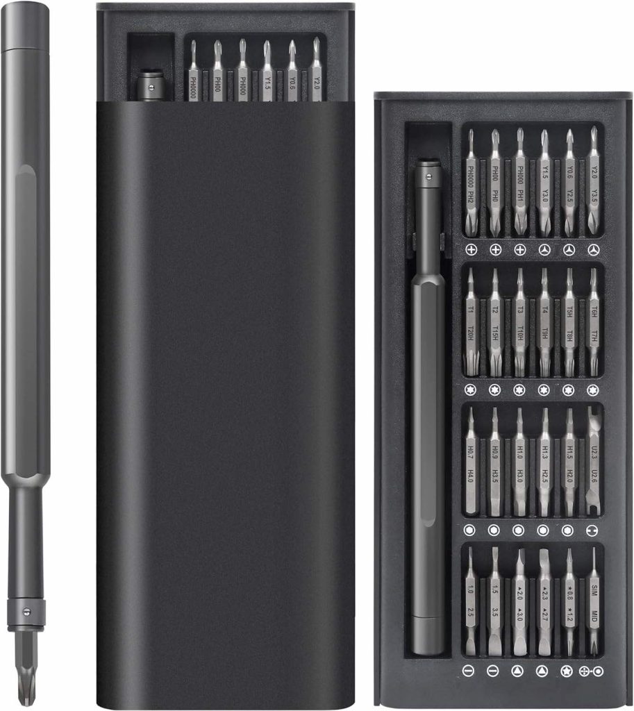
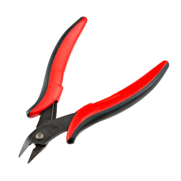
Tools used in this build (not included):
Parts included in Revival Kit for Xplorer Guitar:
- Revival Kit Zeroboard (Strumboard/PCB)
- Revival Kit Fretboard
- 3D Printed Translucent Strumbar for Xplorer
- 5x 3D Printed Translucent Frets (They will be rectangular)
- 5x 3D Xplorer Fret Shims
- 3D Printed Kit Hardware
- Xplorer Breakout Board
- Detachable USB-C Board and bracket
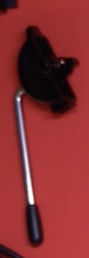
- New Whammy Assembly
- Switch Puller
- Color Coded Wires and Auth Cable
- 10 foot nylon braided USB-A to USB-C cable
- Tube of lubricant


Opening the Guitar
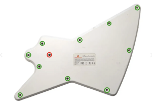
Flip the controller over so the Red Octane sticker on the back of the body is visible. The type of screws used on the outside shells will depend on the model of your guitar:
95055/95605 – PH1 Screws
95157.805 – T10 Screws
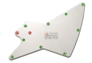
- The screw marked in red is sometimes longer than the others; remember this for when you put everything back together!
- Rear body shell – 11x screws
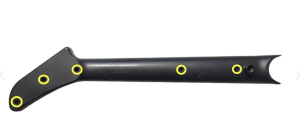
- Rear neck shell – 5x screws
Ensure that all of the screws are removed, and open the shell.
Once the shell begins to open, slowly move down the rest of the shell until it pops open completely.
Repeat this process for the neck, using the opening at the neck connector and working towards the headstock.
If the shell seems to gets stuck, DO NOT FORCE IT. Check to make sure you have removed all of the screws before continuing to pry the shell.
Removal of Original Parts
Now its time to remove the stock boards that will be replaced with the new boards included in the kit.
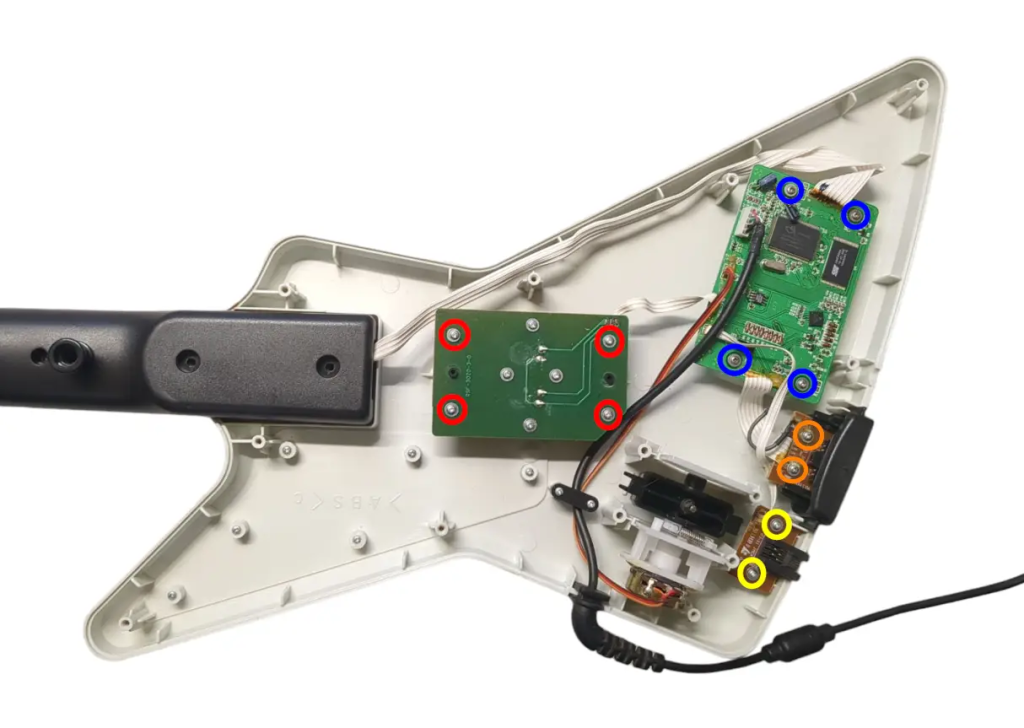
- Remove the 4x screws on the stock Strumboard.
- Remove the 2x screws on the RJ11 port. (This board will not be replaced, so if you’d like to leave it in so there is no open hole in the shell after completing the kit, leave this board installed and cut the wires coming from it instead)
- Remove the 4x screws on the stock input board.
- Remove the 2x screws on the headset port.
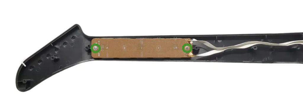
- Remove the 2x screws from the stock Fretboard.
Once all the screws are removed, remove all of the stock boards along with the whammy assembly from the shell.
You will need to keep the following parts of the whammy assembly:
(Optional) Clean Your Guitar
In this step, I took a little bit of time to clean some parts of the guitar. I suggest being more thorough in your build, as your guitar may have finger grime from way back in the day!
A bit of rubbing alcohol and/or soap and water can go a long way. Make sure the parts are fully dry if you clean with soap and water.
Pro tip: Toothbrush, Dawn soap, and water.
Test Your Revival Kit
Before installing the Revival Zeroboard/Strumboard and Revival Fretboard, they should be tested for proper functionality.
- Plug the Revival Fretboard into the Revival Zeroboard/Strumboard using the three included white cables. Make sure that each connection goes to the proper port. It is suggested to go one by one while installing.
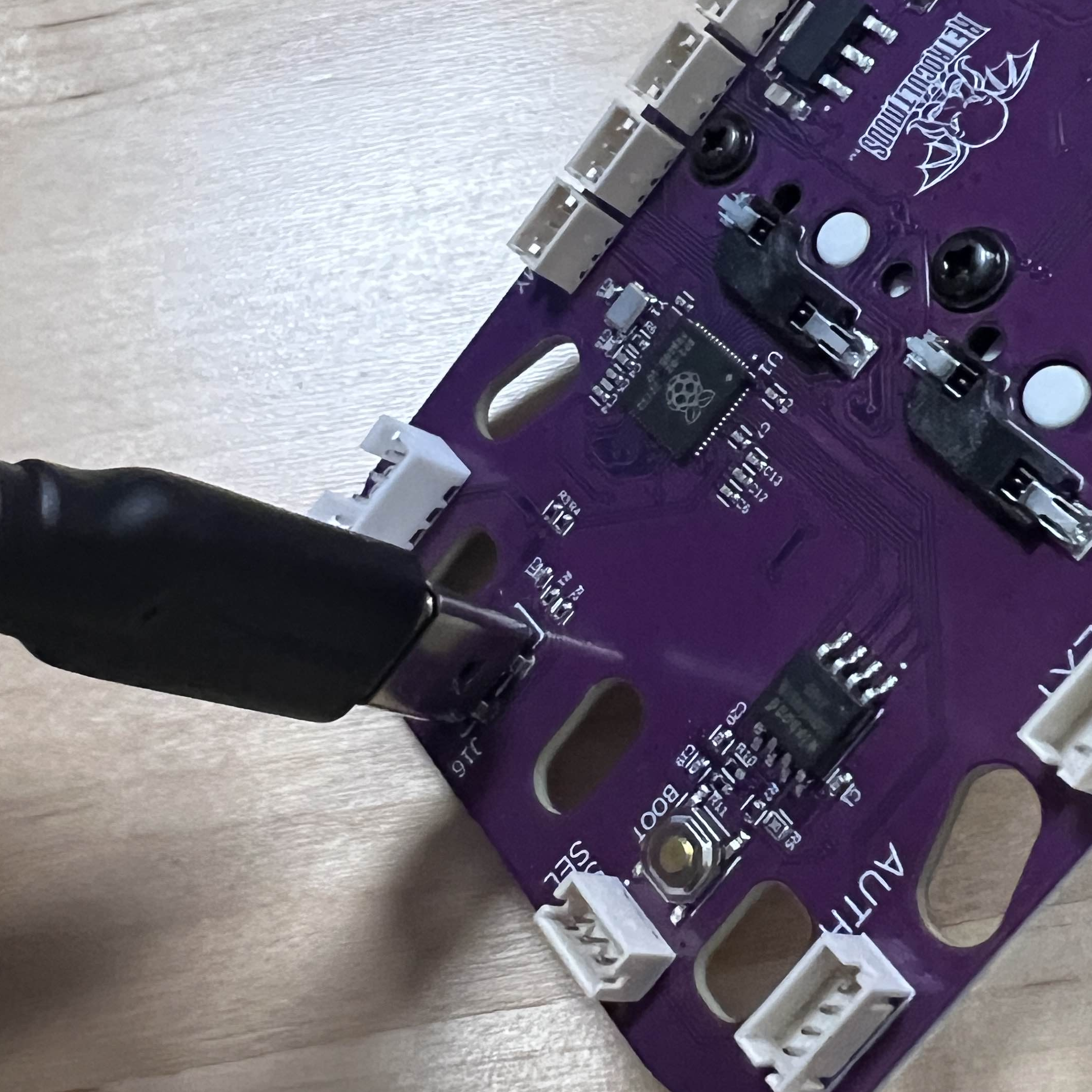
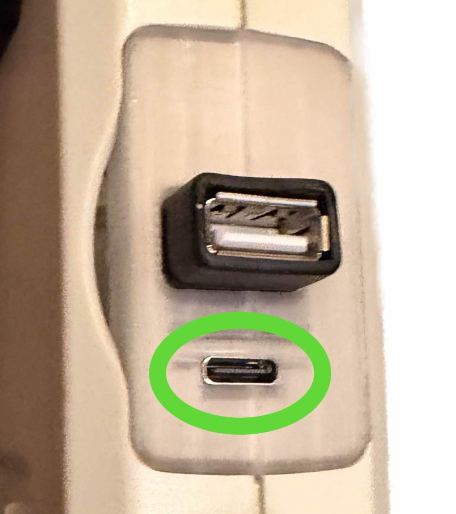
- Plug your Revival Zeroboard/Strumboard into your computer, using the USB-C to USB-A cable included in the Revival Kit. You will plug it into the vertical USB-C port on the Zeroboard.
- Open the RCM Programming Tool (click here to go to the download page)
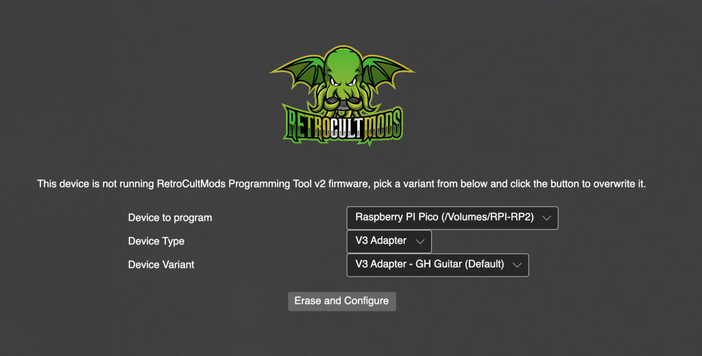
- If the following screen appears for you, make sure to switch the DEVICE TYPE to “Revival Kit”. Click Erase and Configure. Do not touch the device while it is being programmed.
- You will then be brought to this screen, click Configure.
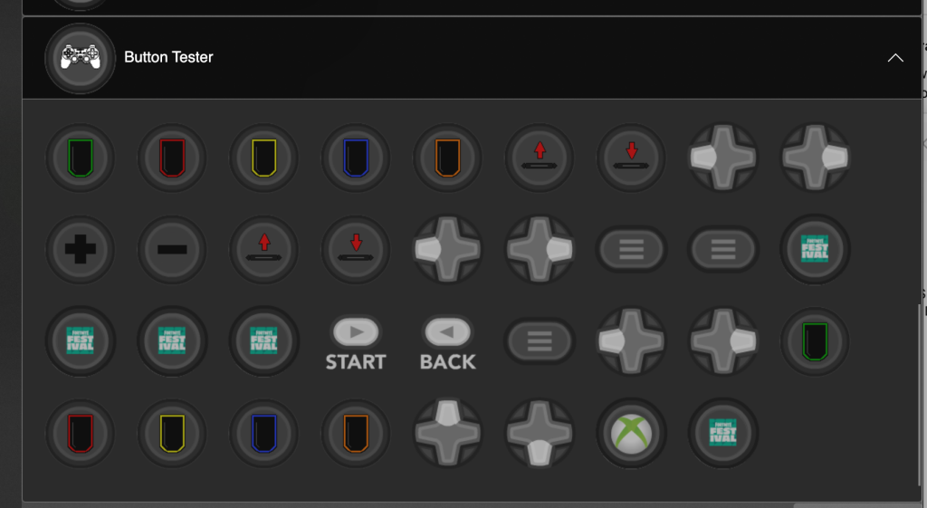
- Scroll down to the list of all inputs and then start pressing the fret and strum switches. The respective switches will light up and so will the input in the RCM Programming Tool. Verify that all of the inputs and switches work properly. If not, contact support.
- Once you’ve verified functionality, move on in the guide!
Prepping the New Strumbar (RGB Only)
IF YOU DID NOT ORDER THE 3D PRINTED CLEAR STRUM BAR, SKIP THIS STEP.
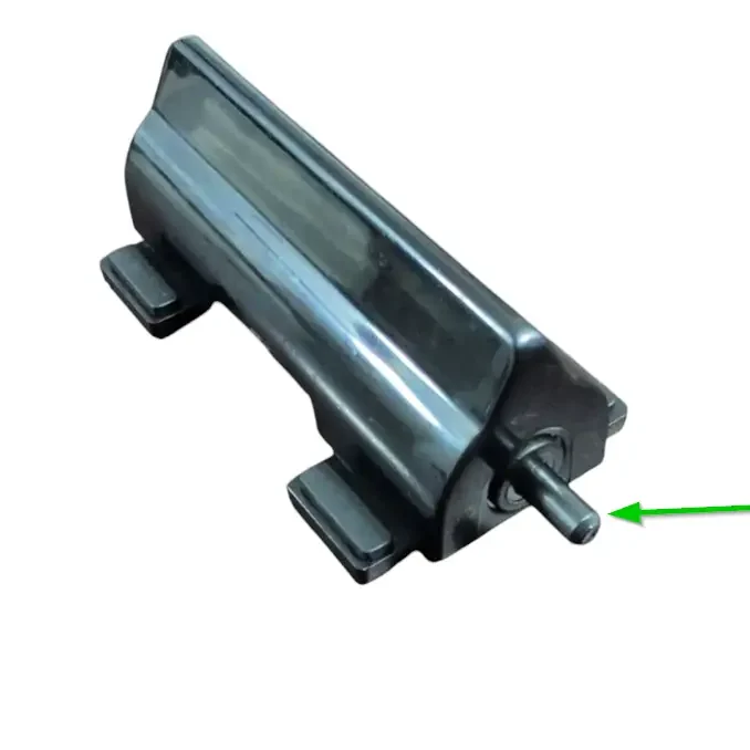
Before installing the new Strumboard, we need to transfer some pieces of the stock strumbar over to the new one:
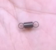
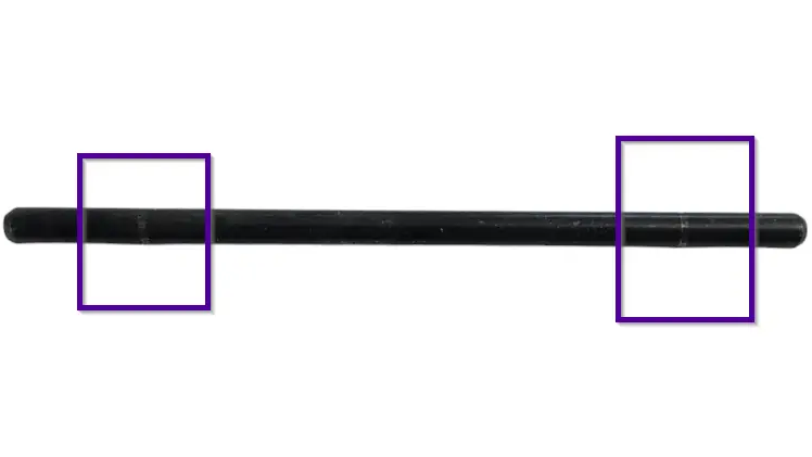
- Remove the metal strumrod by pulling it out of the stock strumbar.
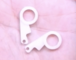
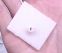
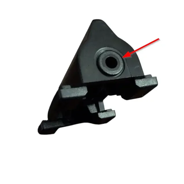
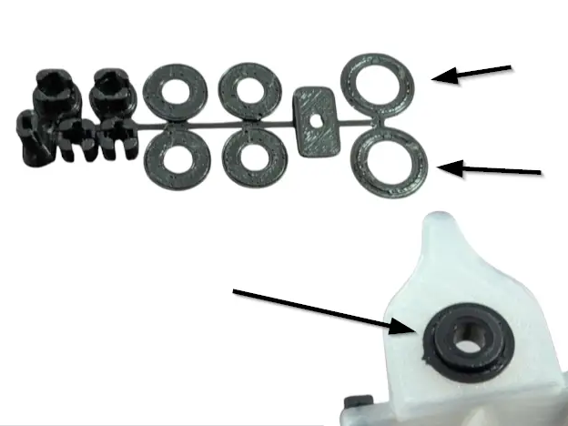
- Remove both of the circular spacers on each end of the strumbar. You can easily remove these by pushing them out with your finger from the inside of the strumbar.
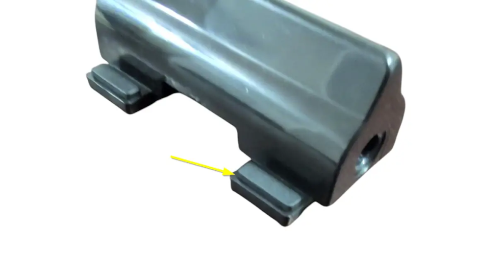
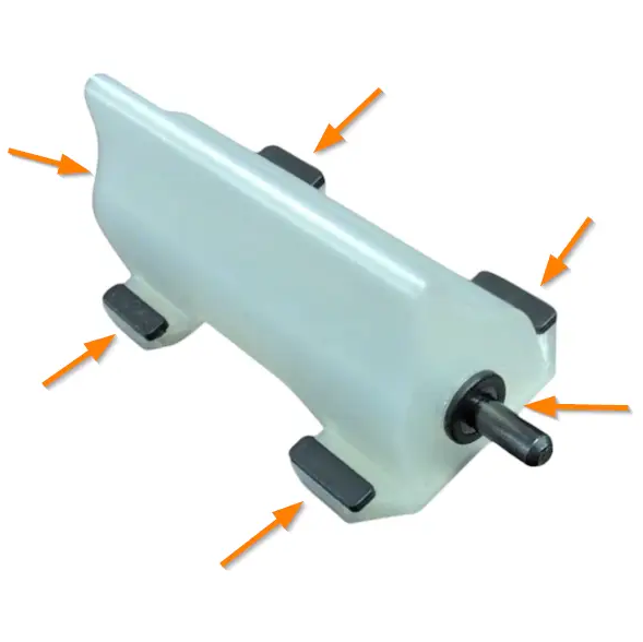
- Remove the four rubber pads on each foot of the strumbar. These can be lifted straight out of their slots.
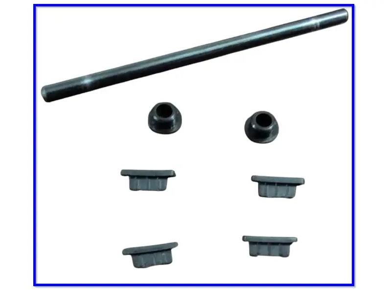
- Make sure you have all the stock parts you need:
- 1x Metal strumrod
- 2x Circular spacers
- 4x Rubber pads
- Find the white tube of lubricant and apply a very small amount on each end of the metal strumrod, where it makes contacts with the circular spacers. Use for finger or a qtip to spread the lubricant out; we want only a thin layer of lubricant on the ends of the strumrod!
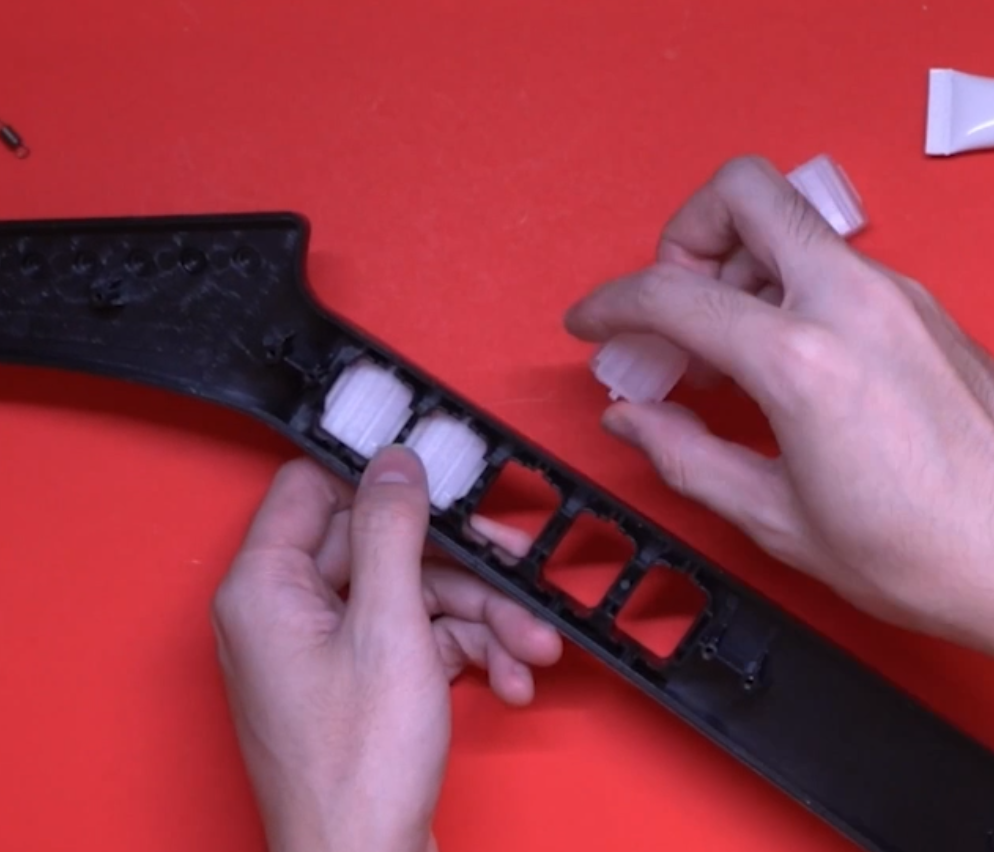
- Put all of these parts into the new strumbar, in the same places as the stock strumbar. Insert the rubber pads into the slots in each of the feet of the new strumbar, insert the spacers into the circular cutouts on each end of the new strumbar, then insert the metal strumrod through the spacers.
- If the strumbar slides up and down the metal rod too much for your liking, then you can install the wide, thin spacers included on the end of the component piece to fill in the gap. Place these under the stock strumbar spacers. You may need to stack multiple on each end to get your desired tolerance!
Installing the Revival Zeroboard (strumboard)
With the stock boards removed, we can now install the new strumbar and strumboard.
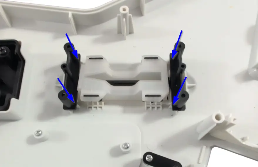
- Slide the metal rod into the new strumbar. Then place the new stumbar into the slot that the stock strumbar sat in. Put the black brackets back into place.
- Separate the small strum keycaps from the component piece and slot them into the stems of the strum switches. This is needed for a tighter strumbar feel.
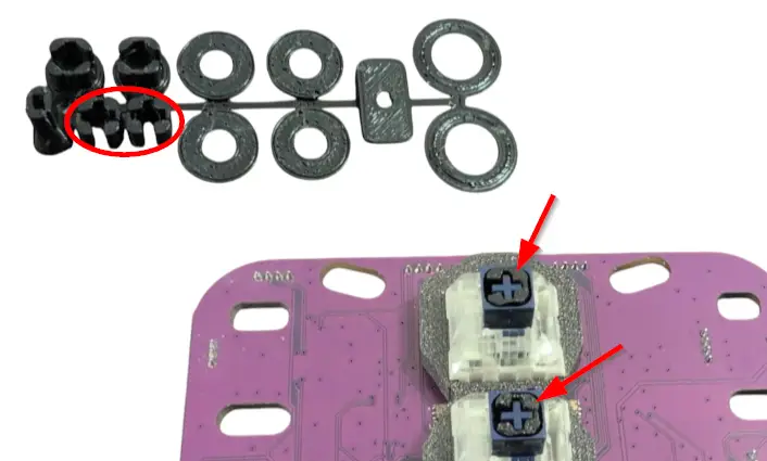
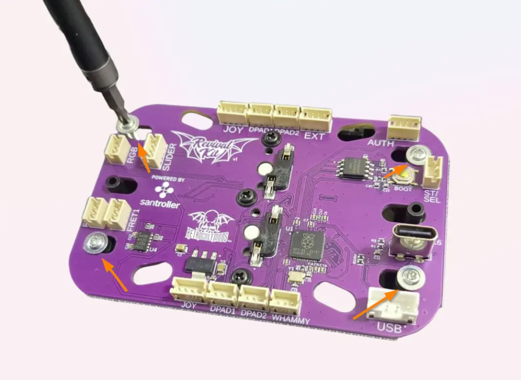
- Place the new strumboard on top of the black brackets, then screw in the new strumboard. If the stock screws are stripped, you can use the replacement Long Screws provided in the kit. Make sure each screw is snug, but do not over-tighten them, or you may scratch away the soldermask of the new strumboard!
Installing the Revival Fretboard
Now its time to install the new RGB Mechanical Fretboard.
Gather the Revival Kit Fretboard, Translucent Frets, 3 White Wires, and 2 Long Screws.
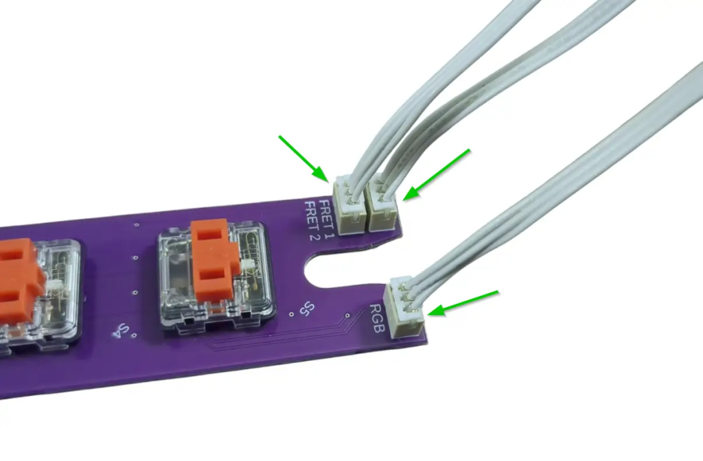
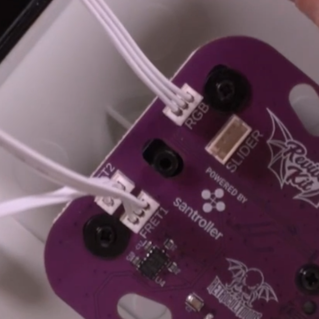
- Connect one end of each of the White Wires into the RGB, FRET1, and FRET2 connectors on the Fretboard. Connect the other end of each White Wire to the corresponding RGB, FRET1, and FRET2 connectors on the Strumboard. I recommend doing one wire at a time to prevent mixing them up.
- Remove the stock frets and replace them with the translucent 3D printed frets provided in the kit. These frets must be used even if you do not want to use LEDs; the stock frets will not fit with the new Fretboard.
Model 95065 Xplorers will need to use the included fret shims to fit properly. Other models will not need shims.
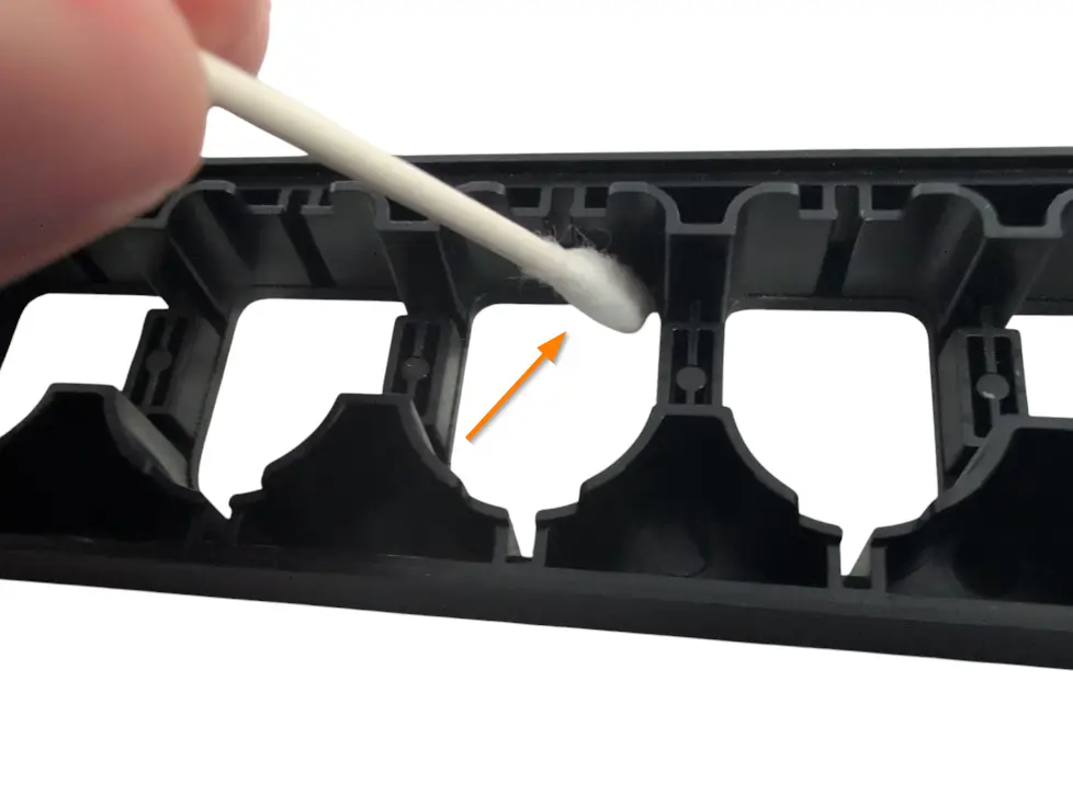
- Remove the stock silicone pad and frets if they are still in the fret slots. Wipe the inside of the fret slots clean if they are dirty. Then apply a small amount of lubricant to your finger or a qtip and lightly coat the inside of the fret slots with lubricant. Make sure to wipe away any excess lubricant that my have spilled to the front of the neck shell!
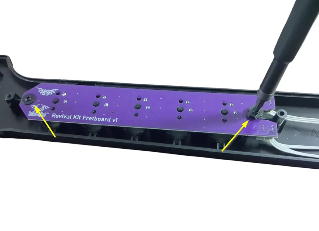
- Place the new Fretboard onto the screw standoffs that the stock fretboard used to sit on (the red switches and white connectors should be facing down towards the Translucent Frets. Use 2 Long Screws to secure the new Fretboard.
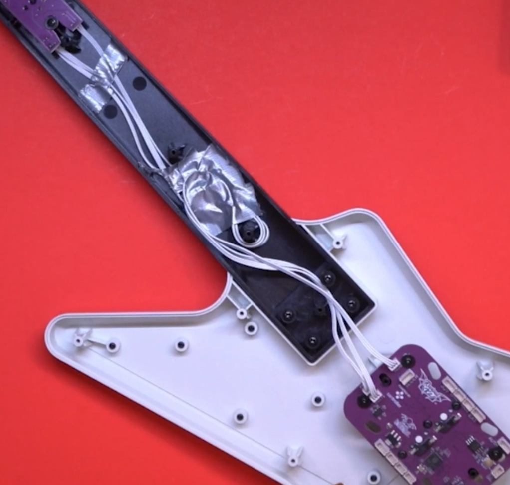
- Route the White Wires through the neck and down through the body. Make sure they are clear of any screw standoffs so they are not damaged when reinstalling the neck shell. Using a bit of tape to hold down the wires internally can help with management.
Installing the Xplorer Breakout Board
Now its time to install the Xplorer Breakout board.
Gather the Xplorer Breakout board (labelled 1X) and 4 Long Screws. Stock screws can also be used if they are not stripped
- Make sure the rubber dome pads are still in place, then install the Xplorer Breakout board where the stock input board used to sit. Use the stock screws or included Long Screws to secure it.
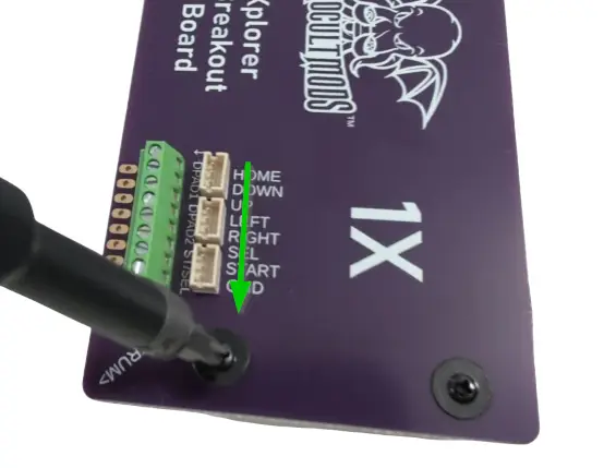
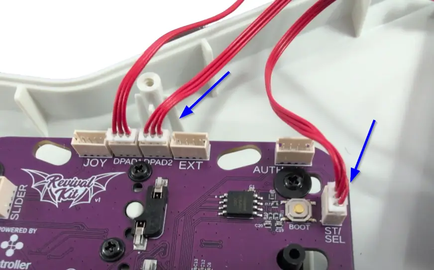
- Connect three red wires into the three white connectors on the Xplorer Breakout board.
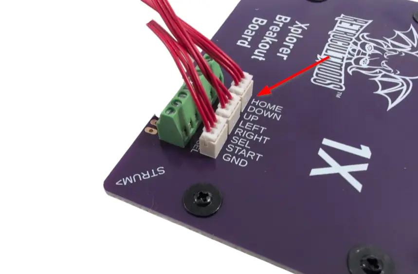
- Connect the other ends of the red wires into their matching connectors on the Zeroboard. Double check the labels on each board and make sure the wires are going to matching connectors!
Assembling and Installing the Whammy
We will need these parts, which we took out during disassembly:
Installing the Authentication Cable and USB-C Port
Installing the Authentication cable is quick and easy.
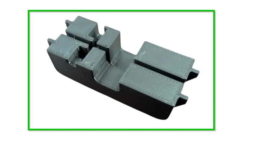
- Gather the Auth/USB-C bracket and break it apart into two separate pieces.
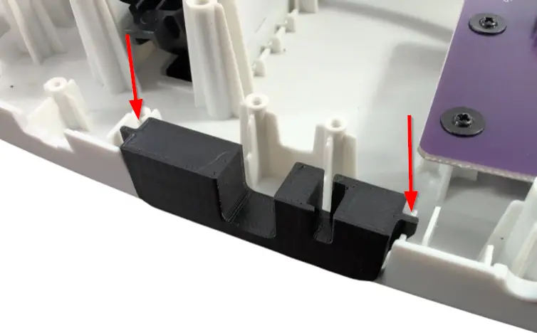
- Slot the bottom bracket into the opening that the headset port used to sit in (use the picture for reference on the orientation of the bracket.
- Gather the Authentication cable and slot it vertically into the wide slot of the bracket. The strain relief should slot between the two existing screw standoffs on the body shell to hold it in place.
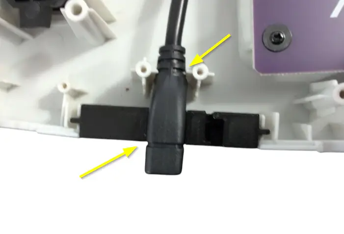
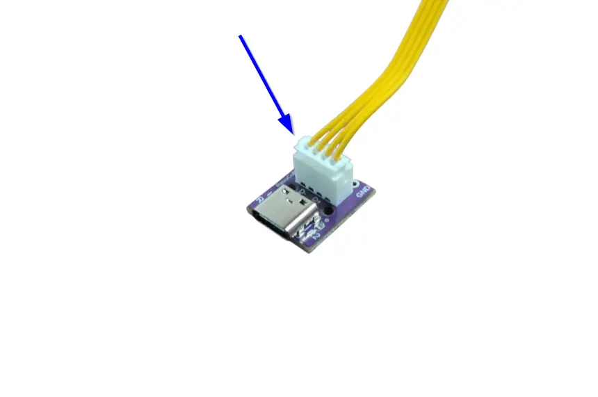
- Gather the yellow cable and the USB-C port board. Plug the yellow wire into the connector on the USB-C port board.
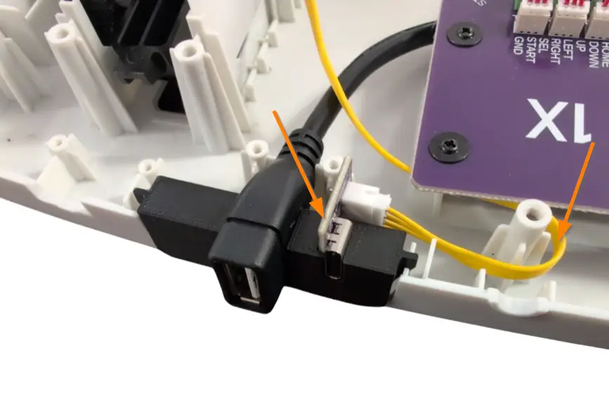
- Slot the USB-C port into the bracket in the orientation as shown in the picture. Wrap the yellow wire around the nearest standoff and route it towards the Zeroboard.
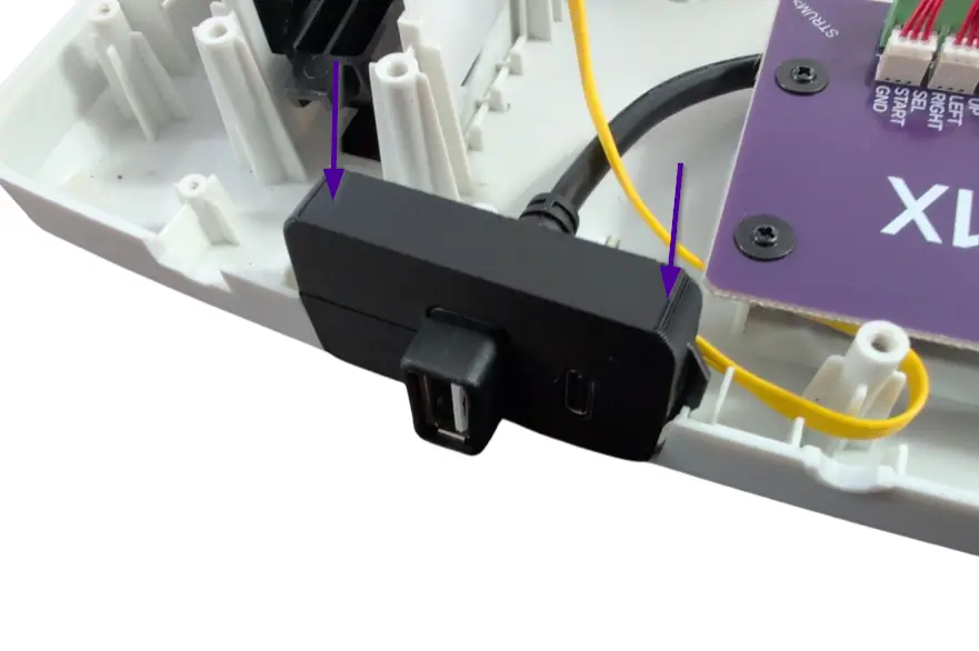
- Slot the top bracket into place, making sure everything is lined up correctly.
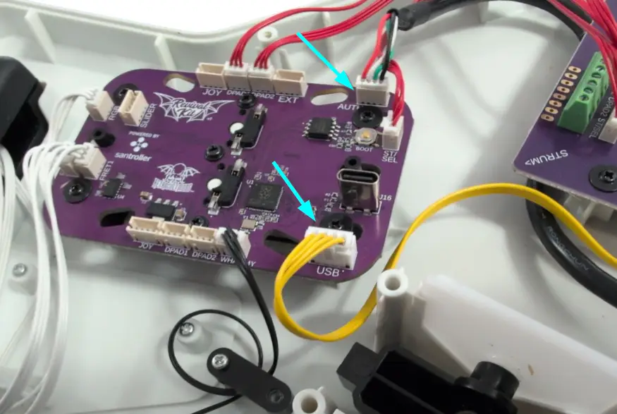
- Plug the yellow wire into the USB connector on the Zeroboard, then connect the Authentication cable into the AUTH connector on the Zeroboard.
(Optional) Test Inputs
- Plug your guitar into your computer using the new USB-C port you installed!
- Open the RCM Programming Tool on your computer (click here to go to the download page)
- If the following screen appears for you, make sure to switch the DEVICE TYPE to “Revival Kit”. Click Erase and Configure. Do not touch the device while it is being programmed.
- You will then be brought to this screen, click Configure.
- Scroll down to the list of all inputs and then start pressing the frets and clicking the strum bar. The respective switches will light up and so will the input in the RCM Programming Tool. Verify that all of the inputs and switches work properly. If not, contact support.
- Once you’ve verified functionality, unplug the guitar and move on in the guide!
Closing the Guitar
You’re almost done! Once you have ensured that each input works, we can close up the guitar!
Make sure none of the wires are in the way of any plastic standoffs, as this will damage them when closing the shell. I would recommend taping down the wires to ensure they are out of the way and not draped across any of the boards.
With the front body and neck shell facing down, put the rear neck shell onto the front neck shell. You will need to apply pressure to close the shell. If you feel like part of the shell will not snap into place, open it up and double check that there is nothing blocking the standoffs. Repeat for the body shell.
DON’T FORGET THE STRAP PEGS!
After both sides are clamped down, install all of the screws you removed earlier:
- Rear neck shell – 5x screws
- Body shell – 11x screws (remember the position of the longer screw, highlighted in red. does not apply to all guitar revisions, but double check your screws!)
Calibrate Tilt and Whammy
Plug the guitar back into your computer and open RCM Programming Tool. Click Configure.
TILT SECTION
- Navigate to the Tilt section and click the arrow to open the menu:
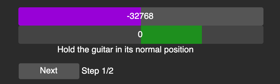
- Click “Calibrate”, then position your guitar in the position you normally play at. Click “Next”.
- Tilt and hold the guitar at the height where you want star power/overdrive to be activated at. Click “Next”.
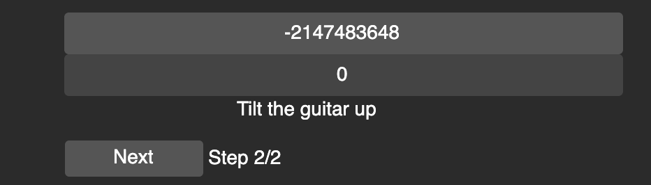
- Your tilt is now calibrated! If you feel like the tilt height is too low or high, recalibrate!
WHAMMY SECTION
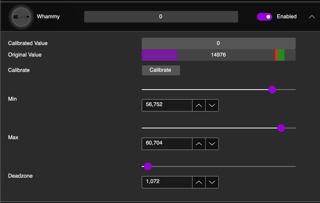
- Navigate to the Whammy and click the arrow to open the menu:
- Click “Calibrate”, then you’ll see text saying ‘Release the whammy’. This means to leave it in it’s up resting position. Click Next.
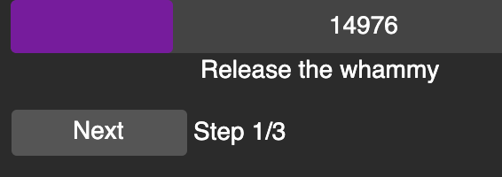
- The text will change to ‘Push the whammy all the way in’. This means the furthest in it can go down without you being forceful. Hold it in that position then click Next.

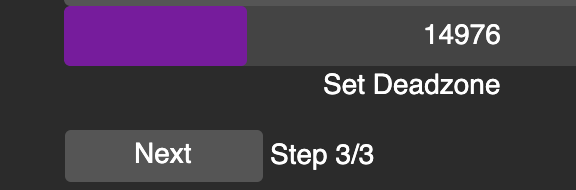
- You must now set a deadzone. This is the distance you need to press inwards before the whammy begins to activate. When you press in the whammy, you will see the bar move and change the desired deadzone. Find your desired distance and hold it there. Use your other hand to click Next.
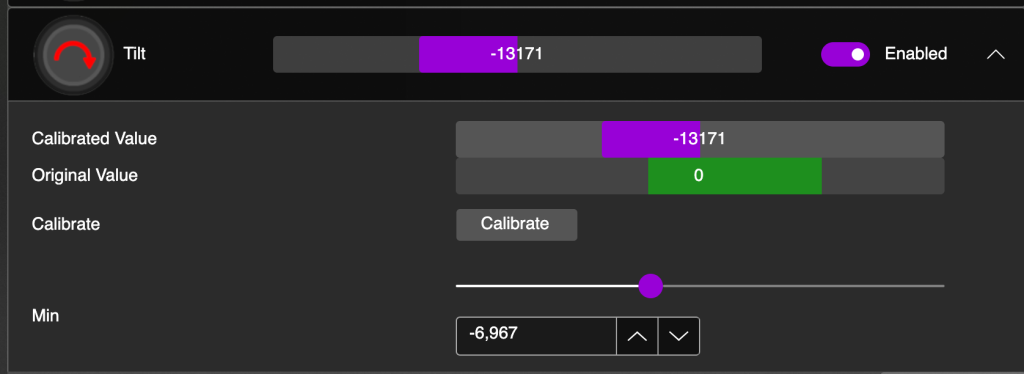
- Now that you have the whammy calibrated, press it in. You will see both the Calibrated Value and Original Value move. The Calibrated Value is what is interpreted by the game. If it is to your liking, you can move on. If not, recalibrate!

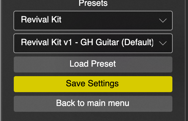
- You are now done calibrating and can Save Settings. Keep the RCM Programming Tool open if you want to configure fret and strum bar colors in the next section.
(Optional) Configure Fret and Strum Bar Colors
- Open RCM Programming Tool if you do not already have it open
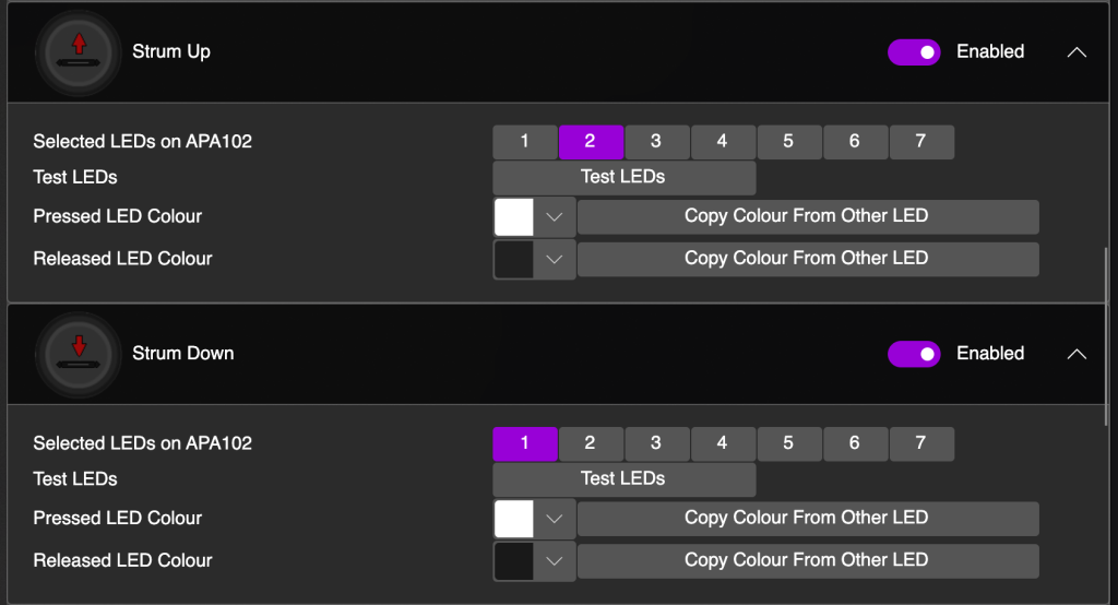
- Scroll to the fret and strum inputs and click the arrow to reveal the color selectors for your chosen input.
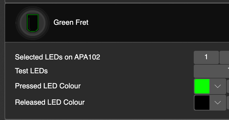
- Click on the arrow for the pressed or released LED color to open the color picker menu:
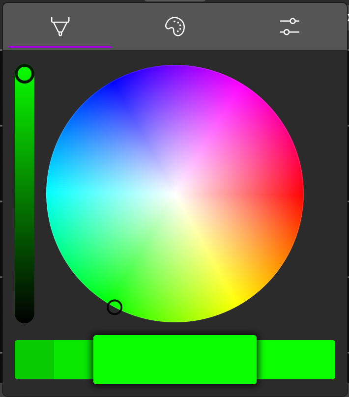
- Change this to whatever color you want!
- Click Save Settings when you’ve configured all of the colors that you want.
Note: The strum bars are the same way.
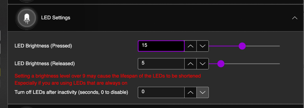
ADJUST BRIGHTNESS (IMPORTANT!)
Navigate to the LED Settings dropdown menu and open it. You will see that both values are set to 31. You will want to lower the released value to under 9. It is suggested to lower the pressed value as well to allow for longer LED lifespan.
Finishing Up, Factory Resets and Updates
To wrap up this installation, the last things to know are how to factory reset and/or update the guitar.
UPDATE
- Download and open the latest RCM Programming Tool
- Plug in your Xplorer via the USB-C port to your computer using the USB-A end of your cable.
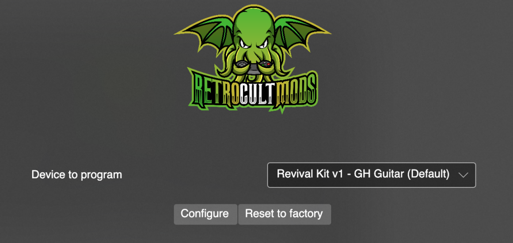
- The RCM Programming Tool will show a device to program, that being the Revival Kit v1. Click Configure.
- Click Save Settings.
FACTORY RESET
- Download and open the latest RCM Programming Tool
- Plug in your Xplorer via the USB-C port to your computer using the USB-A end of your cable.
- The RCM Programming Tool will show a device to program, that being the Revival Kit v1. Click Reset to Factory.
- The following screen will appear. Change the Device Type to Revival Kit.
- Click Erase and Configure.
- You will then be brought back to this screen:
- You are now free to reconfigure the guitar. Do note that tilt and whammy values are reset and will have to be recalibrated.